
I designed the all my models models from a love of flying this type of model and as such I have built and flown several of each of these models over the last few years. The aim of each design is to optimise the performance in the air and ease of use on the ground. Materials, batteries and radio gear move on, the methods shown here are the ones that I do or have used on my own models over recent years.
The build notes here are equally applicable for Saker, Harrier, Falcon and even Wyvern models. There are clearly some differences in the models but the principals and approach suggested here will be a good starting point as you assemble your model. There is no single way of assembling a model and you may feel that you have another- that you prefer. If so- great and please share your ideas with the model flying community.
Wiring Loom
I tend to make my own looms usually with 4x 1m servo extension leads. This gives me with enough wiring and the servo ends I need, already fixed to the wires. I used the Multiplex green 6 pin connectors, with the male half fixed in the fuselage and the female half loose in the wings. Once soldered and tested I suggest some epoxy & microballoons or silicone over the connectors to make the loom more robust. Once fitted in the fuselage there’s not much that can happen to your connectors. As I leave the female connectors loose in the wing I add 5 cm of heat shrink over the wire and connectors for extra support.
Give yourself enough slack so that the looms in the wing stick out far enough to be able to connect the loom halves before the wings get too close to the fuselage- it’s just easier that way and there’s less chance of the ends being pushed into the wing
Wings
The wing assembly is very straight forward. The horns are supplied separately, this gives you the opportunity to use commercial LDS systems or the horns provided wish. I generally use servorahmen LDS systems but The choice is yours.
I have used King max servos for a number of years and for clevis systems or the smaller Falcon they have been excellent. I not use KST and ChaServos for my larger models- to take advantage of their superior hold and torque.
Regardless of the drive system used, I always ad a ply shearweb in the wing near where the servo arm will go. The wings feel rigid and this may be over kill but for a small amount of effort I know when the controls are applied in the air, there will not be blow back.
Clevis method
I have used 2 and 3mm clevises with the supplied horns in the past- they all work very well. I know that I am getting old in my build techniques. If you use clevises rather than LDS, it is likely that you will need to grind some of the clevis off to help it move freely- this is normal. Once the servos and horns are in place. Measure the distance so that the push rods are made up to the correct length.
Here's an illustration from my old Artist instructions, with a nice illustration of the geometry. I grind the flap and aileron clevises.


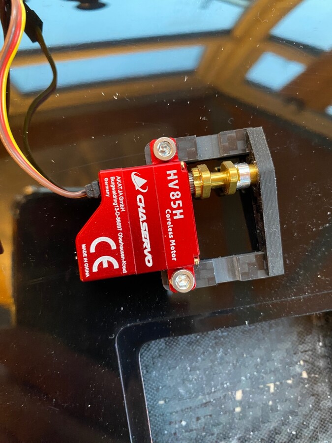


A neat looking servo in situ.

Fuselage
The fuselage assembly
has been made very straight forward thanks to the moulded tray. This holds the servos, switch and ballast tube. The tray does not arrive fixed, making the cuts for the fittings very simple
and safe away from the rest of the fuselage. It also makes threading
those servo wires much more straight forward.

The last Wyvern I built used the CHAservos HV85V servos, it's the speed and centring hold that makes a noticeable difference in the air.

The Ballast tube will slide in place once the servo tray is fixed, it's important that you plan the model's CG and know where the middle of the ballast tube is before you start gluing things in. The ballast tube is provided slightly over sized, this is easy to cut to size. Gluing a piece of dowel in at the back of the tube is also a very simple process.
I fix the ballast tube in place using epoxy and chopped mat. I have found that I need to make a hole in the servo tray for the lock nut to recess into. This does mean that the servo tray is taking the weight of the ballast on landing, so make sure you are happy with it's fixing
A final and possible over kill is to fit a block of wood between the ballast tube and top of the fuselage.
Like all the models I have worked on with Zhou, the ballast tube takes 19mm chrome shower rail perfectly. This gives over 1.2kg of lead ballast and has always been more than enough, although I have used up to 1.8kg of tungsten on the bigger days- Ballistic!
The back of the fuselage is
fully enclosed. Before starting
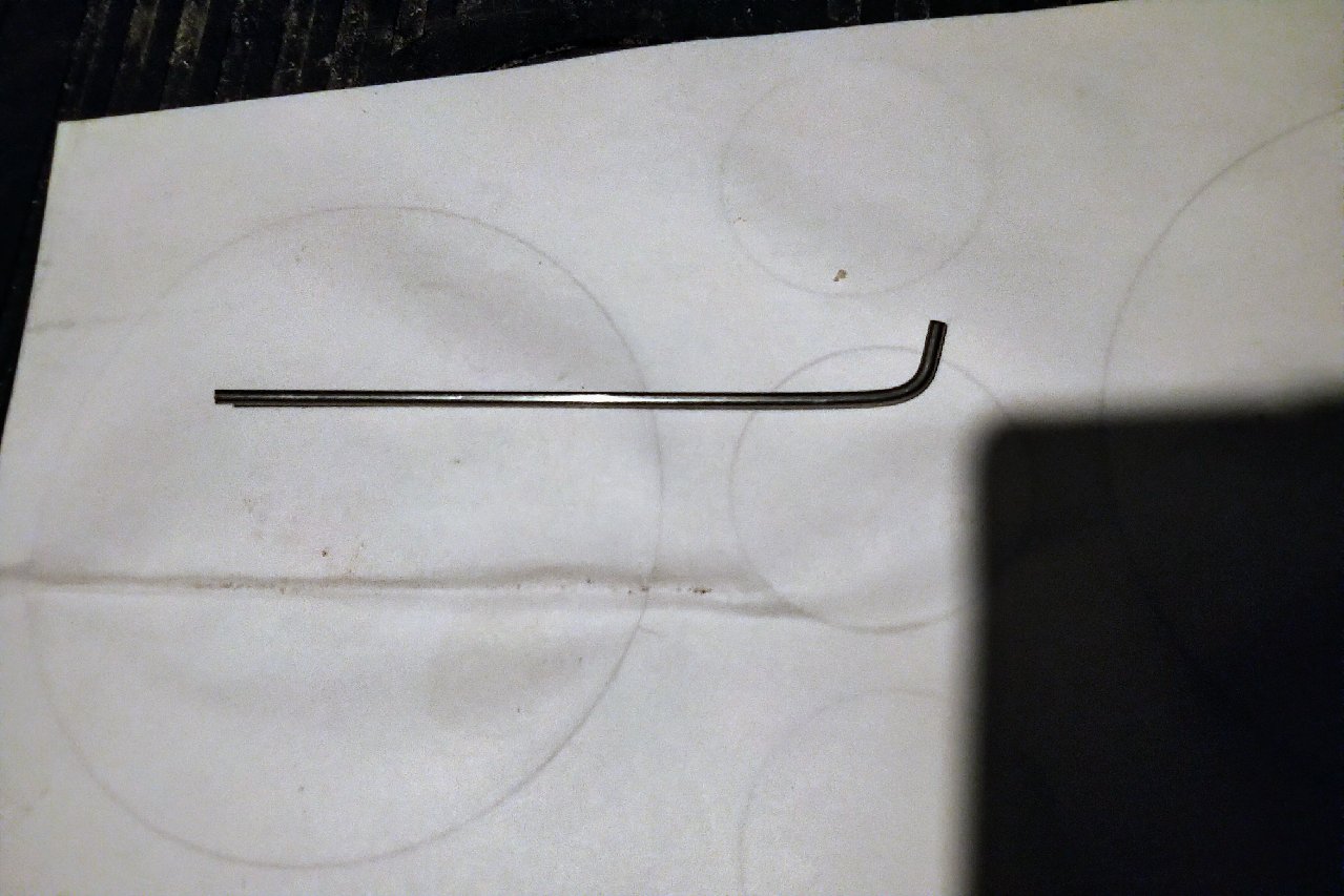
to fit the tail, the 5mm carbon rods need to be fitted and fixed. The easiest way to do this is to drill through the fuselage so that the 5mm
rods span the rear of the fuselage, this is the recommended way and the strongest. This makes for an excellent tail fix as well as adding further strength to
the fuselage.


No comments:
Post a Comment